Home/
Registry/
Ford/
Probe/
1993-1997/
“PAIN WHILE YOU REPAY”/
Photo
supermotors.net/registry/media/621717
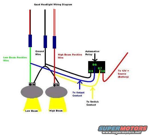
Quad Headlight Wiring Diagram - Relay Terminals 30/85/86/87 (Ford Probe)
Reference · 1993-1997 ProbeAll 65 wiring diagrams

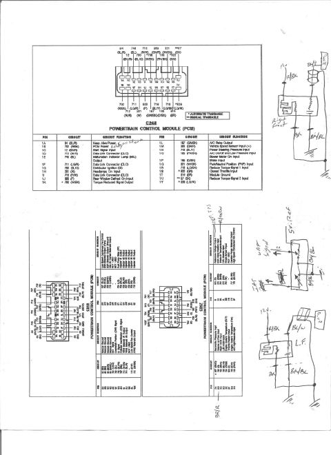
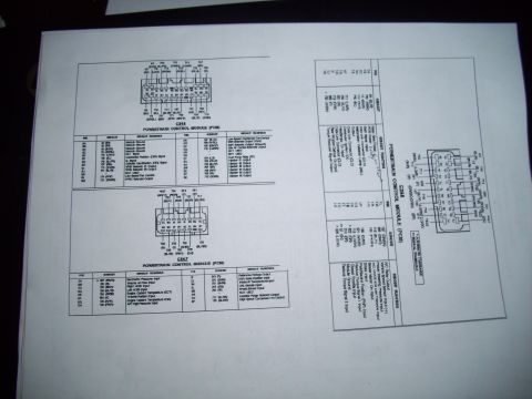
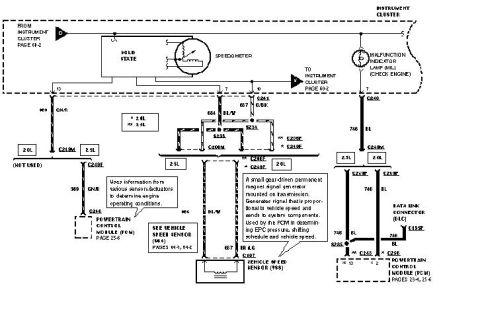
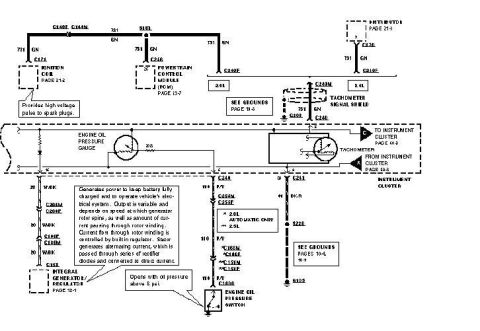
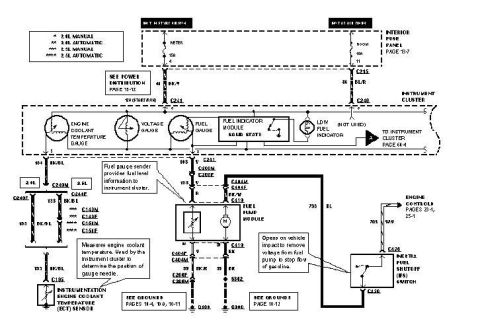
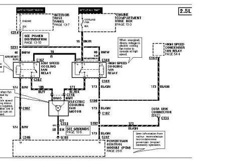
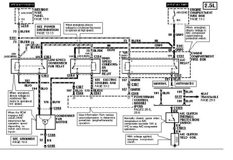
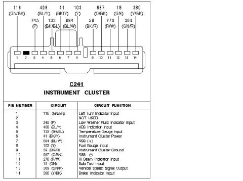
Quad headlight wiring diagram showing low and high beam circuits, ground wire and an automotive relay with terminal numbers.
Part of 1993-1997 Ford Probe Wiring Diagrams
This document is a hand-drawn/computer-illustrated wiring diagram titled 'Quad Headlight Wiring Diagram,' showing how to wire separate low beam and high beam headlight bulbs through an automotive relay. The diagram identifies three primary wires at the top: a Low Beam Positive Wire (shown in green), a Ground Wire (shown in black), and a High Beam Positive Wire (shown in red), each passing through inline connectors (drawn as blue blocks). An automotive relay is depicted with four labeled terminals: 86, 87, 85, and 30. Terminal 30 connects via a red wire to a 12V+ source (battery). A blue wire is labeled 'To Output Contact' and a yellow wire is labeled 'To Switch Contact.' Two headlight bulbs are drawn at the bottom, labeled Low Beam and High Beam, each with positive terminal markings and light output illustrated as yellow beams. A reader can learn the basic relay-based wiring approach for quad (four-lamp) headlight systems, including which relay pins receive battery power, switch signal, and output to the lamps, and how the low beam, high beam, and ground wires route to the bulbs. The document contains no year, make, model, part numbers, fuse ratings, or wire gauge specifications.
Is this accurate? Sign in to help verify it.
Frequently asked questions
- What relay terminals are used in this quad headlight wiring diagram?
- The automotive relay in the diagram uses terminals 86, 87, 85, and 30. Terminal 30 connects to the 12V+ source (battery).
- What wire colors are shown for the headlight circuits?
- The low beam positive wire is green, the ground wire is black, and the high beam positive wire is red. A blue wire goes to the output contact and a yellow wire goes to the switch contact.
- Where does the relay get its power in this diagram?
- A red wire runs from relay terminal 30 to the 12V+ source, labeled as the battery.
- How does the relay connect to the headlight switch?
- A yellow wire from the relay is labeled 'To Switch Contact,' while a blue wire is labeled 'To Output Contact' feeding the headlight circuit.
No comments yet.