Ford Probe VRIS Switching Valve Diagram - Torque vs RPM Intake Operation
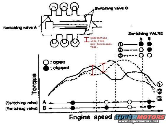
Schematic of intake manifold switching valves (VRIS) with a torque-versus-engine-speed graph and valve open/closed states.
This schematic illustrates the operation of a Variable Resonance Induction System (VRIS) intake manifold with two switching valves (A and B). The top portion shows a cutaway drawing of the intake manifold identifying the locations of Switching valve A and Switching valve B. The main graph plots engine torque versus engine speed (rpm) for three valve configurations: curve ① with both valves closed, curve ② with valve A open and valve B closed, and curve ③ with both valves open. Each configuration produces a torque peak at a different engine speed range, and the system switches valve states as rpm rises (both closed at low rpm, A open at mid rpm, both open at higher rpm, then both closed again at the top) so the engine follows the highest available torque curve. Timelines beneath the graph show the open/closed state of valves A and B across the rpm range. A red annotation added by the uploader highlights the gap between torque curves in the mid-rpm range, labeled 'Substantial loss from non-functional VRIS,' indicating how much torque is lost if the switching valves fail to operate. No year, make, model, or part numbers are stated in the document itself.
Is this accurate? Sign in to help verify it.
Frequently asked questions
- What do the switching valve positions do in the VRIS system?
- The diagram shows three configurations: curve ① with valves A and B both closed, curve ② with A open and B closed, and curve ③ with both open. Each produces a torque peak at a different engine speed, and the system switches states as rpm increases to follow the highest torque curve.
- What happens if the VRIS switching valves don't work?
- The red annotation on the graph marks the gap between the torque curves in the mid-rpm range as 'Substantial loss from non-functional VRIS,' showing engine torque is significantly reduced if the valves fail to switch.
- How do valves A and B change state as engine speed rises?
- Per the timelines under the graph: at low rpm both A and B are closed; at mid rpm A opens while B stays closed; at higher rpm both A and B are open; at the top of the rpm range both close again.
- What do the open and filled circles mean in the diagram?
- The legend states ○ means the switching valve is open and ● means it is closed.
Comments
More from this build


No comments yet.