Ford Probe 2.5L PCM Connector C246 Pinout - Wire Colors & Circuit Functions
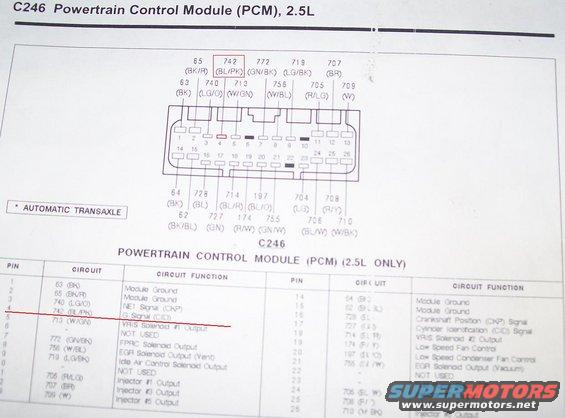
PCM connector C246 pinout diagram for a 2.5L automatic transaxle with wire color codes and a pin-circuit function table.
This document is a factory-style connector pinout page for connector C246, the Powertrain Control Module (PCM) connector on the 2.5L engine (Ford Probe application per uploader). It shows a diagram of the 26-pin PCM connector with each pin's circuit number and wire color code, followed by two tables listing pin number, circuit number/wire color, and circuit function for pins 1-26. Functions include module grounds (pins 1, 2, 14, 15), NE1/CKP signal (pin 3, circuit 740 LG/O), G Signal/CID (pin 4, circuit 742 BL/PK, highlighted in red by the uploader), VRIS solenoid outputs (pins 5 and 18), FPRC solenoid output (pin 7), EGR solenoid vent and vacuum outputs (pins 8 and 21), idle air control solenoid output (pin 9), crankshaft position and cylinder identification signals (pins 16 and 17), low speed fan and condenser fan controls (pins 19 and 20), fuel pump relay (pin 23), and injector outputs for injectors #1-#5 (pins 11-13, 24-26). A footnote reads '* AUTOMATIC TRANSAXLE.' A reader can use this page to identify PCM pin locations, wire colors, and circuit functions for diagnosing 2.5L V6 engine control wiring, particularly the G (CID) signal circuit 742 (BL/PK) that the uploader highlighted.
Is this accurate? Sign in to help verify it.
Frequently asked questions
- What pin is the G Signal (CID) on the 2.5L PCM connector C246?
- Pin 4, circuit 742 with a BL/PK (blue/pink) wire, is the G Signal (CID) input on connector C246.
- Which pins on C246 are module grounds?
- Pins 1 (circuit 63, BK), 2 (65, BK/R), 14 (64, BK), and 15 (62, BK/BL) are all Module Ground circuits.
- What wire color is the crankshaft position (CKP) signal on the 2.5L PCM?
- Pin 16, circuit 728, a BL (blue) wire, carries the Crankshaft Position (CKP) Signal. Pin 3, circuit 740 (LG/O), is labeled NE1 Signal (CKP).
- Which C246 pins are the fuel injector outputs?
- Pin 11 = Injector #1 (705 R/LG), pin 12 = Injector #3 (707 BR), pin 13 = Injector #5 (709 W), pin 24 = Injector #2 (706 BL/W), pin 25 = Injector #4 (708 R/Y), pin 26 = Injector #5 (710 W/BK).
- Which pins on connector C246 are not used?
- Pins 6, 10, and 22 are marked NOT USED.
Comments
More from this build






No comments yet.