SuperMotors SuperMotors SUPERMOTORS Search: try “orange Bronco on 35s”
Home/ Registry/ Ford/ Probe/ 1993-1997/ 1994 Ford Probe/ Photo supermotors.net/registry/media/936139

GM HEI Module Conversion Wiring - Pin W, C, G, B Connections (1994 Ford Probe)
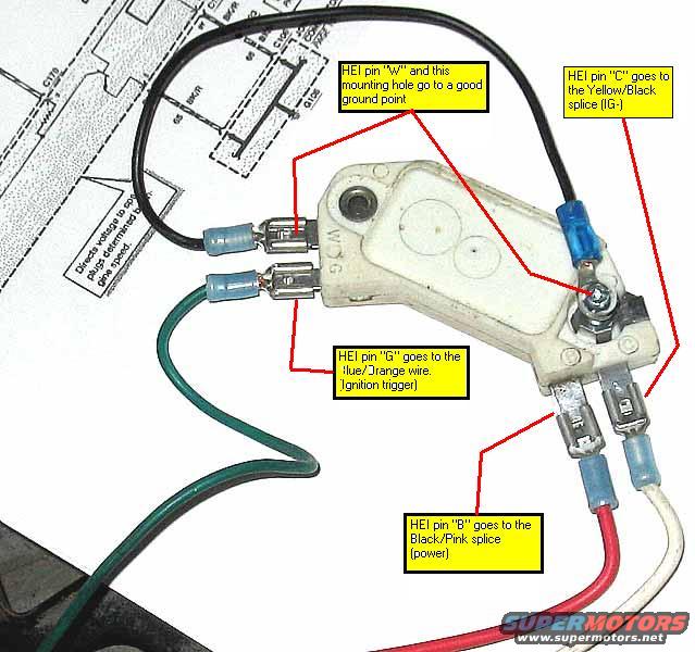
Annotated photo of an HEI ignition module showing pin W, C, G and B wiring
Annotated photo of an HEI ignition module showing pin W, C, G and B wiringOriginal file
Annotated photo of an HEI ignition module showing pin W, C, G and B wiring

Reference · 1993-1997 ProbeAll 65 wiring diagrams

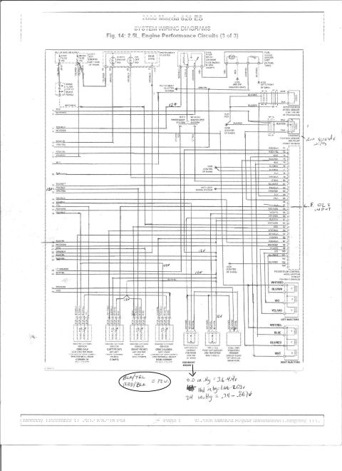
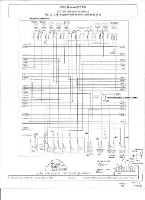
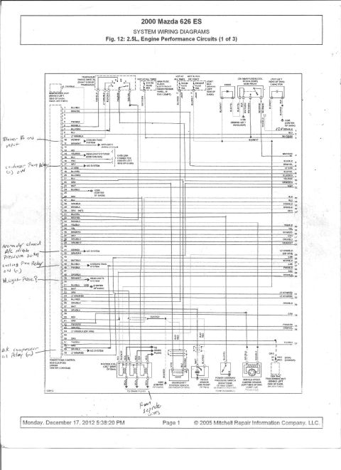
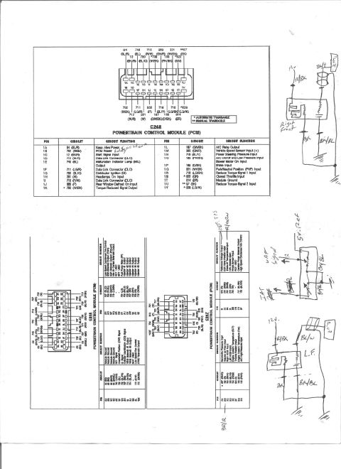
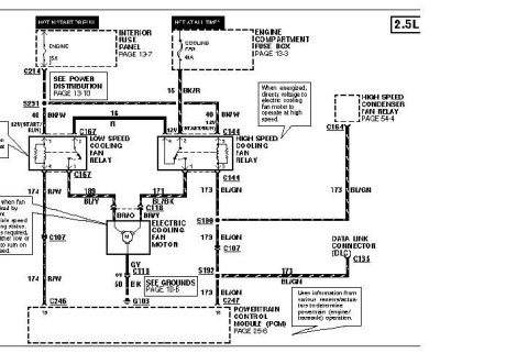
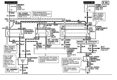
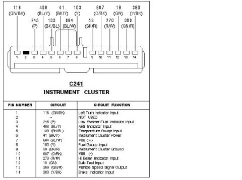
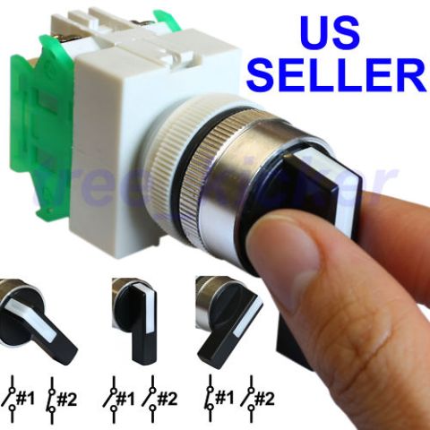
GM HEI Module Conversion Wiring - Pin W, C, G, B Connections (1994 Ford Probe) 2000 Mazda 626 2.5L Engine Performance Wiring Diagram - PCM Pins & O2 Sensors 2000 Mazda 626 ES 2.5L Engine Performance Wiring Diagram (2 of 3) - PCM & EGR 2000 Mazda 626 ES 2.5L Engine Performance Wiring Diagram - PCM Pinout (1 of 3) Ford Probe PCM Connector Pinouts C248, C246, C247 - Wiring Diagram & Pin Table 1993 Ford Probe PCM Connector Pinouts C247 C248 C249 - Wiring Diagram Speedometer circuit wiring diagram with VSS, PCM, check engine MIL and data link connector 1996 Ford Probe Instrument Cluster Wiring Diagram - Tach, Oil Gauge, Alternator 1996 Ford Probe Instrument Cluster Wiring Diagram - Fuel & Temp Gauge Circuits 1993-1994 Ford Probe 2.5L Cooling Fan Wiring Diagram - Relays, PCM & Fuses 1994 Ford Probe 2.5L Condenser Fan & A/C Clutch Wiring Diagram Ford Probe C241 Instrument Cluster Connector Pinout - Wire Colors & Functions 65wiring diagrams1993-1997 Ford Probe More reference 3-Position Rotary Selector Switch: Contact Positions #1 & #2 DiagramBrochure Tachometer Output from Coil Negative - 1N4004 Diode Rev Counter SchematicSchematic AutoAlliance International vehicle certification label dated 11/23/94 with GVWR and GAWR ratingsSpec plate 1995 Probe manual transaxle assembly procedure pages with shift lever and reverse lever stepsService procedure Manual transaxle specifications screen with lubricant grade, 2.0L and 2.5L gear ratios and differential shim sManual page 1995 Ford Probe Multi-Stage Boost Control Vacuum Routing Diagram - Wastegate SetupVacuum routing Hub Spacer Ring Blueprint - Ø77.75 OD x Ø72.00 ID x 6.35 Thick (Ford Probe)Blueprint Exhaust Manifold & Turbocharger Exploded Diagram with Torque Specs (AC210648AB)Exploded parts Connecting Rod Bolt Torque Specs & Clearances - 8740 Cap Screw Instruction SheetTorque spec

Annotated photo of an HEI ignition module identifying pins W, C, G, and B and their wire connections.

Part of 1993-1997 Ford Probe Wiring Diagrams

AI caption · Photo 38 of 44

This document is an annotated photograph showing how to wire a GM HEI ignition module for an ignition conversion. The white HEI module is shown resting on top of a printed factory wiring diagram, with blue and red crimp-on spade terminals attached to its pins. Four yellow callout boxes with red pointer lines identify each connection point: HEI pin "W" and the module's mounting hole must both go to a good ground point; HEI pin "C" connects to the Yellow/Black splice (labeled IG-); HEI pin "G" connects to the Blue/Orange wire, which serves as the ignition trigger; and HEI pin "B" connects to the Black/Pink splice, which supplies power. Wire colors visible in the photo include black (ground), green, red, and white leads terminated with insulated crimp connectors. The underlying wiring diagram fragment mentions directing voltage to the spark plugs as determined by engine speed and shows connector/ground designations such as C178 and G102. A reader can learn the exact HEI module pin assignments (W, C, G, B) and which vehicle wire splice each pin must be connected to when performing this HEI module ignition retrofit.

Is this accurate? Sign in to help verify it.

Frequently asked questions

Where does HEI pin "W" connect?
HEI pin "W" and the module's mounting hole both go to a good ground point.
Which wire does HEI pin "C" connect to?
HEI pin "C" goes to the Yellow/Black splice, labeled IG-.
What is HEI pin "G" used for?
HEI pin "G" goes to the Blue/Orange wire, which is the ignition trigger.
Where does the HEI module get power?
HEI pin "B" goes to the Black/Pink splice, which is the power connection.
Comments

No comments yet.

More 1993-1997 Probes