1997 Ford Probe 2.5L Grounds Wiring Diagram - G104 G105 G106, PCM & HO2S
Reference · 1993-1997 ProbeAll 65 wiring diagrams
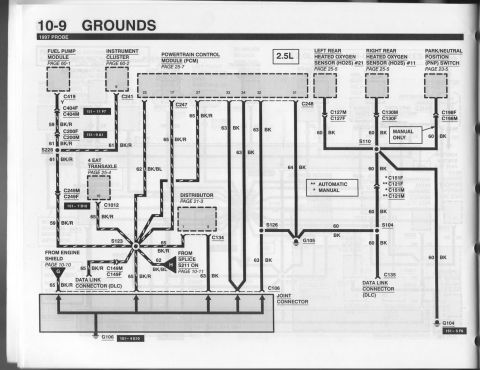

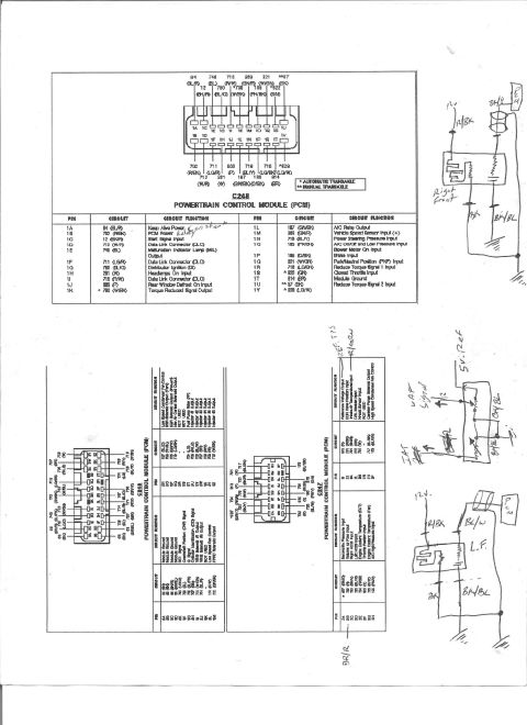
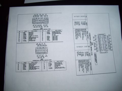
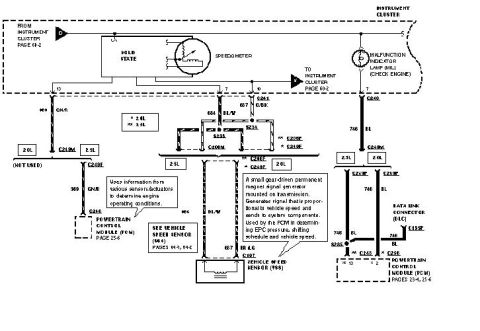
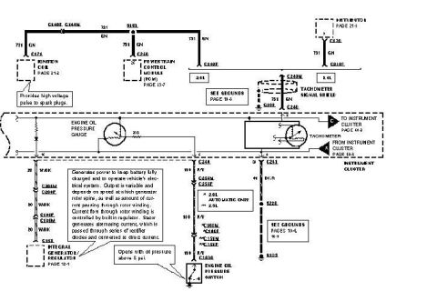
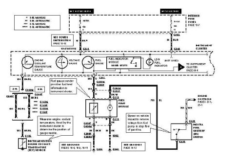
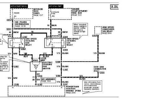
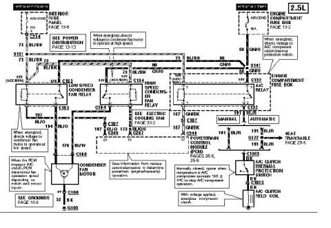
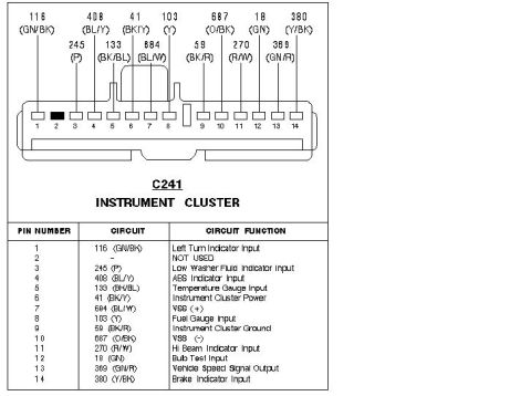





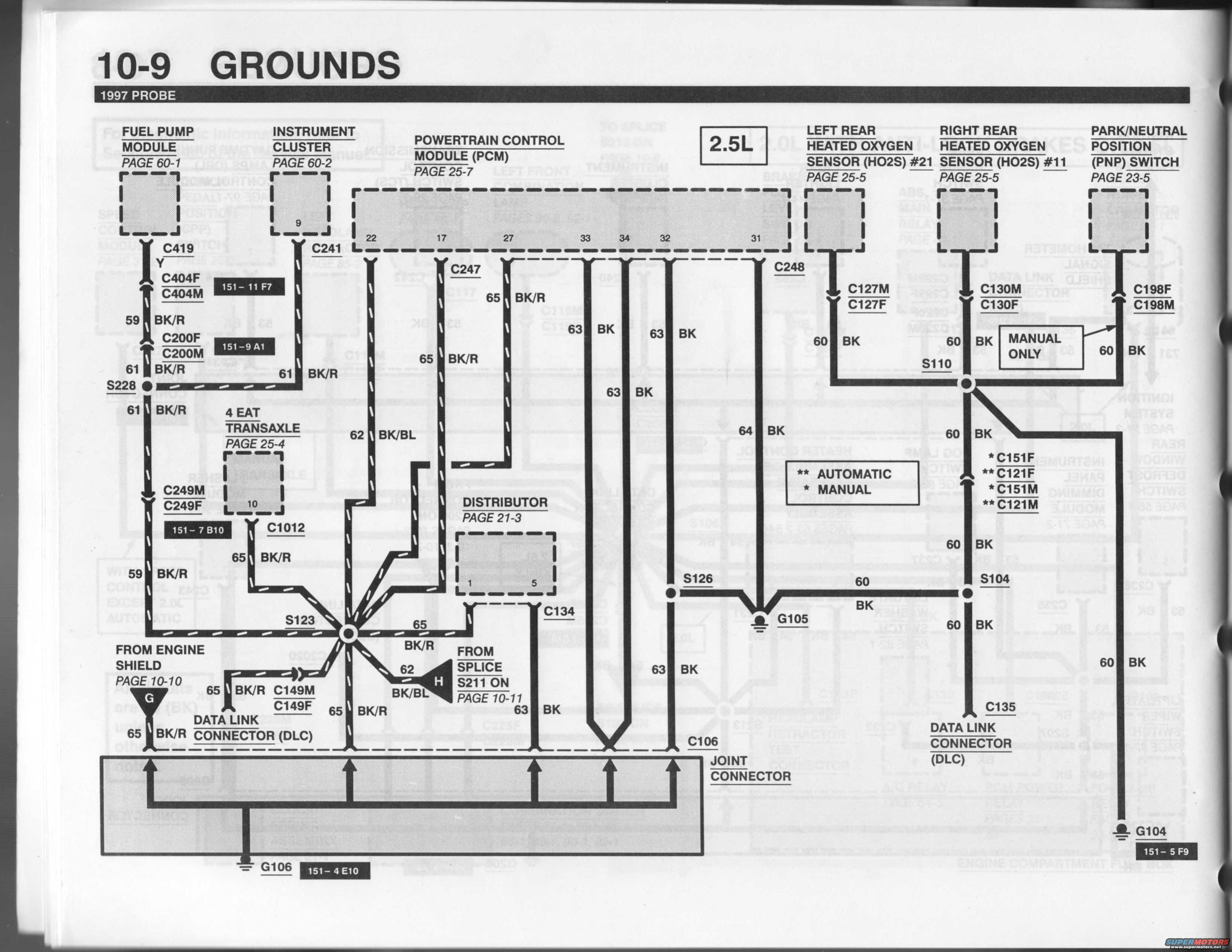
Service-manual wiring diagram of the 1997 Probe ground circuits showing the PCM, sensors, connectors and ground points.
Part of 1993-1997 Ford Probe Wiring Diagrams
This is page 10-9, "GROUNDS," from the 1997 Ford Probe electrical wiring diagram manual, covering the 2.5L engine ground distribution circuit. The diagram traces ground wiring from major components, fuel pump module (page 60-1), instrument cluster (page 60-2), powertrain control module/PCM (page 25-7, pins 22, 17, 27, 33, 34, 32, 31), 4EAT transaxle (page 25-4), distributor (page 21-3), left and right rear heated oxygen sensors HO2S #21 and #11 (page 25-5), and the park/neutral position (PNP) switch (page 23-5, manual transmission only), down to ground points G104, G105, and G106 via the C106 joint connector. Wire circuits shown include 59 BK/R, 61 BK/R, 62 BK/BL, 63 BK, 64 BK, 65 BK/R, and 60 BK, with numerous connectors (C419, C404F/M, C200F/M, C241, C247, C248, C249M/F, C1012, C127M/F, C130M/F, C198F/M, C149M/F, C134, C135, C151F/M, C121F/M) and splices (S228, S123, S126, S110, S104). Automatic (**) versus manual (*) transmission variations are noted. Cross-references point to the engine shield ground (page 10-10) and splice S211 (page 10-11). Locator codes such as 151-11 F7, 151-9 A1, 151-7 B10, 151-4 E10, and 151-5 F9 identify connector/ground positions.
This document covers 1997, which may differ from this 1996 Ford Probe.
Is this accurate? Sign in to help verify it.
Frequently asked questions
- What ground points are shown in the 1997 Probe 2.5L grounds diagram?
- Ground points G104 (locator 151-5 F9), G105, and G106 (locator 151-4 E10), with many circuits joining at the C106 joint connector before reaching ground.
- Which PCM pins are grounded on the 1997 Probe 2.5L?
- The diagram shows PCM ground pins 22, 17, 27, 33, 34, 32, and 31, using circuits such as 65 BK/R, 62 BK/BL, 63 BK, and 64 BK.
- What wire colors are used for the ground circuits?
- Circuits shown include 59 BK/R, 61 BK/R, 62 BK/BL, 63 BK, 64 BK, 65 BK/R, and 60 BK (black and black/red, black/blue wires).
- How are the rear heated oxygen sensors grounded?
- Left rear HO2S #21 grounds through connectors C127M/C127F and right rear HO2S #11 through C130M/C130F, each on 60 BK circuits leading through splices S110/S126 to ground G105.
- Is the park/neutral position (PNP) switch ground the same for automatic and manual?
- No: the C198F/C198M connection to the PNP switch is labeled 'MANUAL ONLY,' and the legend marks * MANUAL and ** AUTOMATIC variants (e.g., C151F/M vs C121F/M).






No comments yet.