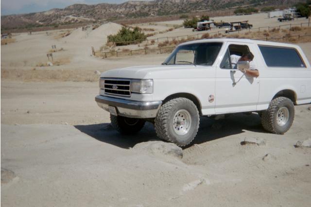
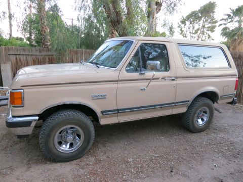
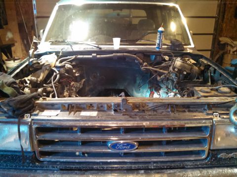
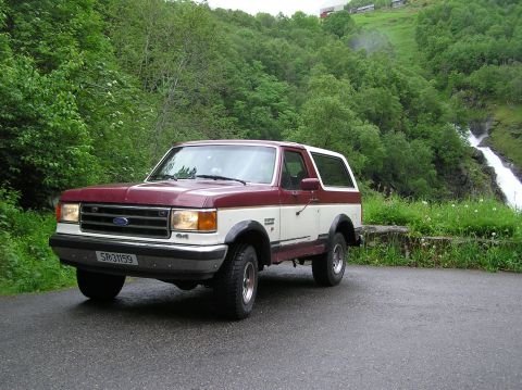
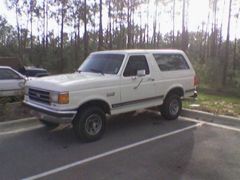
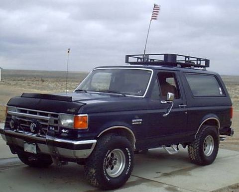
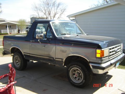
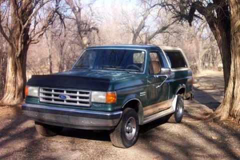
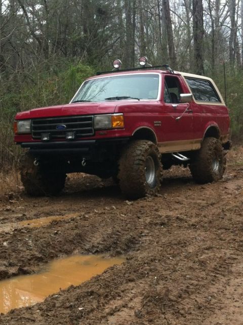
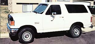
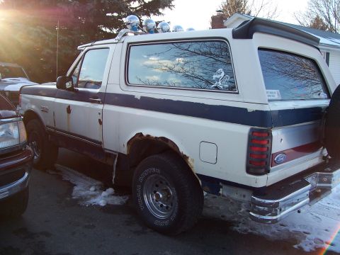
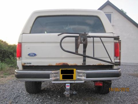
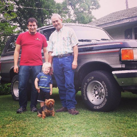
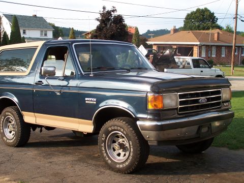
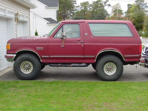
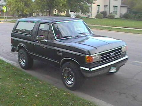
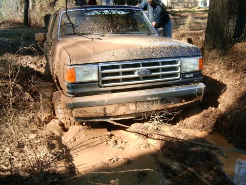
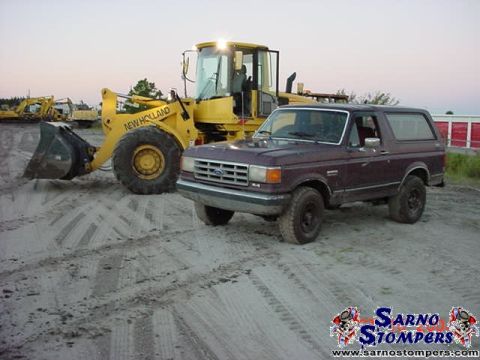
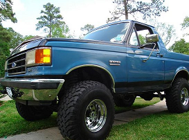
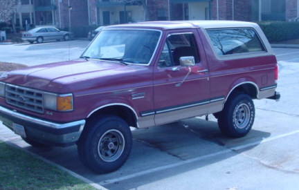
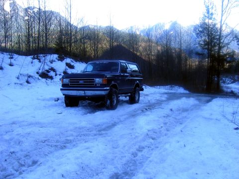
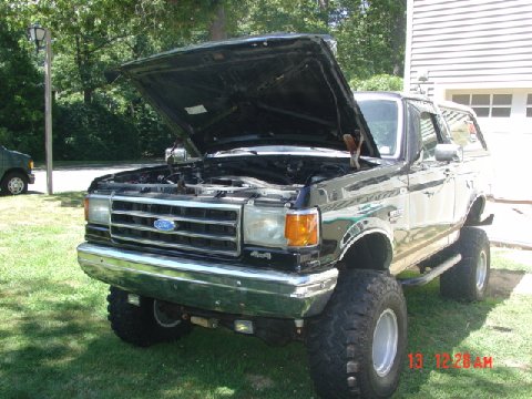
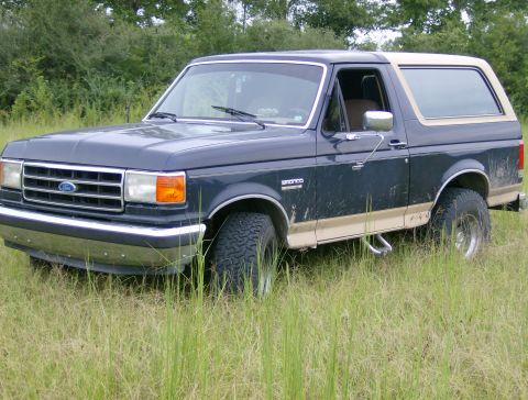
The fourth-generation Ford Bronco ran from 1987 through 1991 on the redesigned F-series "Bricknose" body, named for the flush, aerodynamic front clip with flush headlamps that replaced the boxy Bullnose face. For 1987 Ford gave the 4.9L (300) inline-six electronic fuel injection and added rear-wheel anti-lock brakes (RABS) as standard equipment, two of the generation's defining mechanical changes; the 5.0L (302) V8 carried over its existing electronic (throttle-body) fuel injection from the third generation. The optional 5.8L (351 Windsor) V8 stayed carbureted for 1987 and received EFI for the 1988 model year. The engine roster carried the 4.9L (300 cubic inch) inline-six as the base unit, with the 5.0L (302) and 5.8L (351 Windsor) V8s optional. The Bronco kept its full-size two-door wagon body with a removable fiberglass rear hardtop over a 104.7-inch wheelbase, sharing its structure with the F-150 ahead of the B-pillar. Twin-Traction Beam (TTB) independent front suspension carried over from the third generation, as did the basic engine family, so the 1987 changes were fuel injection, braking, and styling rather than a new chassis. The Mazda-built M5OD five-speed overdrive manual replaced the older four-speed manual around 1988, and the biggest later mechanical addition was the E4OD four-speed overdrive automatic for 1990. The base trim was called Custom for 1987 and was renamed XL for 1988; above it sat the better-equipped XLT and the upscale Eddie Bauer.
At a glance
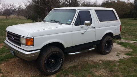
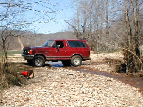
- Years: 1987-1991 (fourth generation, "Bricknose")
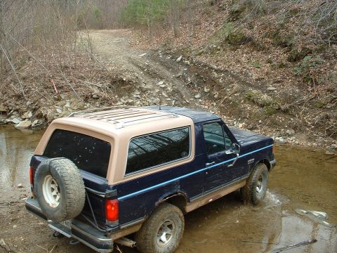
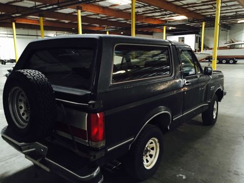
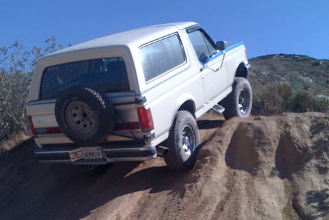
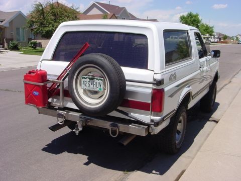
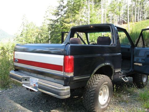
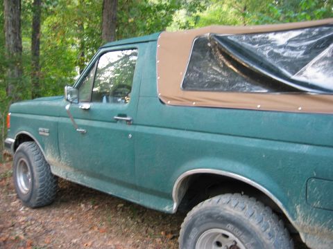
- Body style: two-door full-size wagon with removable fiberglass rear hardtop, 104.7-inch wheelbase
- Engines: 4.9L (300) inline-six, 5.0L (302) V8, 5.8L (351 Windsor) V8
- Fuel system: electronic fuel injection on the 4.9L six from 1987; the 5.0L V8 carried over its existing fuel injection; the 5.8L V8 was carbureted in 1987 and gained EFI for 1988
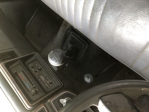
- Transmissions: 4-speed and 5-speed manuals, 3-speed and 4-speed automatics; the Mazda-built M5OD 5-speed overdrive manual replaced the 4-speed manual around 1988, and the E4OD 4-speed automatic arrived for 1990
- Front suspension: Twin-Traction Beam (TTB) independent front axle, carried over from the third generation
- Brakes: front disc, rear drum, with rear-wheel anti-lock brakes (RABS) standard from 1987
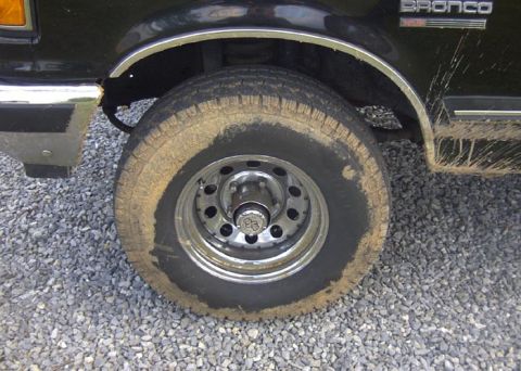
- Axles: Dana 44 TTB front axle; Ford 8.8-inch semi-floating rear axle
- Trims: base trim (Custom for 1987, renamed XL for 1988), XLT, Eddie Bauer
Year-by-year changes
| Year | Engines | Drivetrain & brakes | Notable changes |
|---|---|---|---|
| 1987 | 4.9L (300) six gains fuel injection; 5.0L (302) V8 fuel-injected (carried over); 5.8L (351W) V8 carbureted | Manual and automatic options; Dana 44 TTB front axle; Ford 8.8-inch semi-floating rear; front disc/rear drum with standard rear-wheel ABS (RABS) | Bricknose redesign: flush aerodynamic front end, electronic fuel injection on the 4.9L six, and standard rear-wheel anti-lock brakes |
| 1988 | 4.9L (300) six, 5.0L (302) V8, 5.8L (351W) V8, all fuel-injected | Dana 44 TTB front axle; Ford 8.8-inch semi-floating rear; front disc/rear drum with rear-wheel ABS | 5.8L V8 gained multi-port EFI, completing the fuel-injected lineup; the Mazda-built M5OD 5-speed overdrive manual replaced the 4-speed manual around this year; the base trim was renamed from Custom to XL |
| 1989 | 4.9L (300) six, 5.0L (302) V8, 5.8L (351W) V8, fuel-injected | Dana 44 TTB front axle; Ford 8.8-inch semi-floating rear; front disc/rear drum with rear-wheel ABS | Mostly carryover; continued running changes to interior and equipment |
| 1990 | 4.9L (300) six, 5.0L (302) V8, 5.8L (351W) V8, fuel-injected | E4OD 4-speed electronic automatic introduced; Dana 44 TTB front axle; Ford 8.8-inch semi-floating rear; front disc/rear drum with rear-wheel ABS | Arrival of the E4OD overdrive automatic transmission |
| 1991 | 4.9L (300) six, 5.0L (302) V8, 5.8L (351W) V8, fuel-injected | E4OD available; Dana 44 TTB front axle; Ford 8.8-inch semi-floating rear; front disc/rear drum with rear-wheel ABS | Final year of the Bricknose Bronco before the 1992 OBS fifth-generation redesign; the blacked-out "Nite" appearance package was offered |
Engines and drivetrain
The fourth-generation Bronco (1987-1991) used three gasoline engines. For 1987 the 4.9L six gained electronic fuel injection and the 5.0L V8 carried over its existing electronic (throttle-body) fuel injection, while the 5.8L V8 was still carbureted and did not get EFI until the 1988 model year. The base 4.9L inline-six (300 cubic inches) was a long-running, low-revving truck engine valued for torque and durability. The optional 5.0L (302) and 5.8L (351 Windsor) small-block V8s gave more power for towing and the Bronco's roughly 4,500-pound curb weight. Manual and automatic transmissions were offered through the run. Around 1988 the Mazda-built M5OD five-speed overdrive manual replaced the older four-speed manual, and the significant automatic change came for 1990, when Ford introduced the E4OD, a four-speed electronically controlled automatic with overdrive that replaced the older three-speed automatic in many configurations. All 1987-1991 Broncos were built as four-wheel-drive trucks, with standard part-time four-wheel drive and a two-speed transfer case.
Axles and suspension
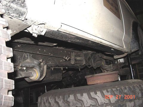
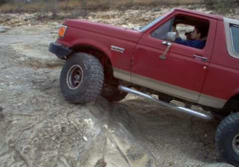
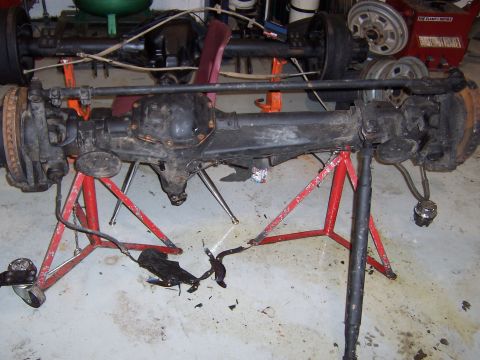
The 1987-1991 Bronco carried over the Twin-Traction Beam (TTB) independent front suspension that the third-generation Bronco had introduced for 1980. TTB uses two long swing arms (beams) pivoting near the frame's centerline, giving each front wheel independent travel while retaining a live-axle-style design with coil springs up front. Four-wheel-drive Broncos paired TTB with a Dana 44 front axle, while the rear axle was a Ford 8.8-inch semi-floating unit. The Ford 8.8-inch rear axle replaced the 9-inch rear axle used by the previous generation. The TTB layout improved ride quality over a solid front axle but is known among owners for camber change during suspension travel and for alignment quirks, traits that carried straight into this generation from the Bullnose era.
What changed for 1987 versus what carried over
Two features were genuinely new to the Bronco for 1987: electronic fuel injection on the 4.9L six, and standard rear-wheel anti-lock brakes (RABS), a rear-axle ABS system that helped prevent rear-wheel lockup under hard braking on a vehicle prone to light rear loading. The 5.0L V8 carried over its existing electronic (throttle-body) fuel injection from the third generation rather than gaining it for 1987. The 5.8L V8 stayed carbureted for 1987 and joined the fuel-injected lineup for the 1988 model year. The Bricknose front-end styling, with its flush composite headlamps and smoother aerodynamic nose, was also new for 1987 and shared with the F-series trucks. By contrast, the TTB front suspension, the two-door wagon body, the 104.7-inch wheelbase, and the basic 4.9L/5.0L/5.8L engine family were carried over from the 1980-1986 third generation. Buyers researching this generation should not credit 1987 with the TTB suspension itself, which debuted in 1980.
Body and trims
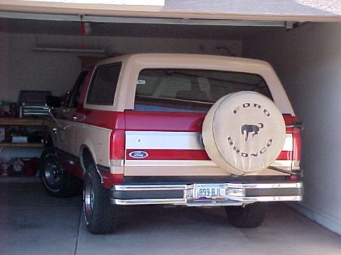
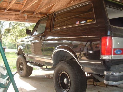
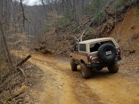
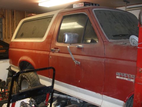
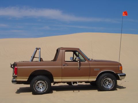
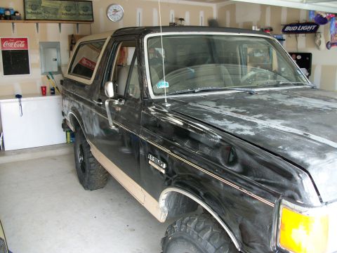
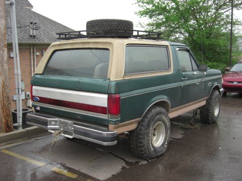
Every 1987-1991 Bronco was a full-size two-door wagon with a removable fiberglass top over the rear cargo and seating area, a body shared structurally with the F-150 ahead of the B-pillar. Trim levels ran from the base trim, called Custom for 1987 and renamed XL for 1988, through the better-equipped XLT to the top Eddie Bauer, the latter typically distinguished by two-tone paint, special wheels, and upgraded interior trim. For 1991 a blacked-out "Nite" appearance package was also offered. The Bricknose interior was updated alongside the F-series, with revised dashboards and switchgear over the run. The rear hardtop remained removable for open-air use, a defining trait the Bronco kept until the 1996 end of the full-size line.
What to know when buying a 1987-1991 Bronco
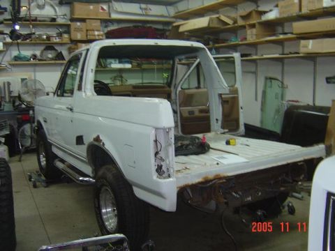
On a fourth-generation Bronco, the early multi-port fuel injection is generally reliable but depends on aging sensors, wiring, and the throttle body staying clean; driveability faults on these trucks often trace to vacuum leaks and worn sensors rather than the core EFI. The TTB front end's pivoting beams and the associated camber bushings and ball joints wear, producing tire wear and alignment drift, so inspect front-end components and tire condition. Rust in the rear quarters, tailgate, and around the removable top's mounting points is the most common structural concern on survivors. On 1990-1991 trucks the E4OD automatic is robust when serviced but expensive to rebuild, so confirm clean fluid and proper shifting.
Frequently asked questions
What is the "Bricknose" Bronco?
"Bricknose" is the enthusiast nickname for the 1987-1991 Ford F-series and Bronco, referring to the flatter, more aerodynamic front clip with flush headlamps that replaced the 1980-1986 "Bullnose" face. The fourth-generation Bronco (1987-1991) wears this Bricknose front end.
What engines did the 1987-1991 Bronco use?
The 1987-1991 Bronco offered the 4.9L (300 cubic inch) inline-six as the base engine and the 5.0L (302) and 5.8L (351 Windsor) V8s as options. For 1987 the 4.9L six gained electronic fuel injection and the 5.0L V8 carried over its existing fuel injection, while the 5.8L V8 was carbureted until it gained EFI for the 1988 model year.
When did the Ford Bronco get fuel injection and anti-lock brakes?
For 1987, the first year of the fourth generation, the Bronco's 4.9L six received electronic fuel injection and the truck gained standard rear-wheel anti-lock brakes (RABS); the 5.0L V8 carried over its existing fuel injection. The 5.8L V8 was still carbureted in 1987 and received EFI for the 1988 model year. RABS is a rear-axle ABS system that reduces rear-wheel lockup under hard braking.
When did the Bronco get the E4OD automatic transmission?
Ford introduced the E4OD, a four-speed electronically controlled automatic with overdrive, on the Bronco for 1990. It replaced the older three-speed automatic in many configurations during the final years of the fourth generation.
Did the 1987-1991 Bronco have independent front suspension?
The 1987-1991 Bronco used Twin-Traction Beam (TTB) front suspension, a beam-type independent design with coil springs. TTB was not new to this generation; it carried over from the third-generation Bronco, which introduced it for 1980.
Sources
- Ford factory shop manuals, parts catalogs, and Bronco/F-series owner literature for the 1987-1991 model years
- VIN and door data plate decoding for engine, axle, and trim verification
- Established Bronco reference works, owner registries, and enthusiast technical resources
- Period road tests and Ford sales/spec material for the fourth-generation full-size Bronco
Asked all the time
What is the "Bricknose" Bronco?
"Bricknose" is the enthusiast nickname for the 1987-1991 Ford F-series and Bronco, referring to the flatter, more aerodynamic front clip with flush headlamps that replaced the 1980-1986 "Bullnose" face. The fourth-generation Bronco (1987-1991) wears this Bricknose front end.
What engines did the 1987-1991 Bronco use?
The 1987-1991 Bronco offered the 4.9L (300 cubic inch) inline-six as the base engine and the 5.0L (302) and 5.8L (351 Windsor) V8s as options. For 1987 the 4.9L six gained electronic fuel injection and the 5.0L V8 carried over its existing fuel injection, while the 5.8L V8 was carbureted until it gained EFI for the 1988 model year.
When did the Ford Bronco get fuel injection and anti-lock brakes?
For 1987, the first year of the fourth generation, the Bronco's 4.9L six received electronic fuel injection and the truck gained standard rear-wheel anti-lock brakes (RABS); the 5.0L V8 carried over its existing fuel injection. The 5.8L V8 was still carbureted in 1987 and received EFI for the 1988 model year. RABS is a rear-axle ABS system that reduces rear-wheel lockup under hard braking.
When did the Bronco get the E4OD automatic transmission?
Ford introduced the E4OD, a four-speed electronically controlled automatic with overdrive, on the Bronco for 1990. It replaced the older three-speed automatic in many configurations during the final years of the fourth generation.
Did the 1987-1991 Bronco have independent front suspension?
The 1987-1991 Bronco used Twin-Traction Beam (TTB) front suspension, a beam-type independent design with coil springs. TTB was not new to this generation; it carried over from the third-generation Bronco, which introduced it for 1980.
Technical Reference
Member-uploaded diagrams & documents for this generation. AI-classified; community-verified where badged.
Data/Spec Plates
- Holmes Hobbies HV500 servo retail-case spec label: 6.0-8.4V, dead band 2us, up to 500 oz-in stall torque at 8.4V, 0.11s/60deg speed, 41x20x40mm, 73g.
- Virtual Dyno torque/power/AFR/boost chart from CSV logs: about 332 hp at 5447 rpm and 351 lb-ft at 4290 rpm with peak boost around 13 psi.
- Virtual Dyno chart plotting torque, power, air/fuel, and boost vs engine RPM: ~335 HP at 4734 rpm and ~413 lb-ft at 3625 rpm.
- California Smog Check report showing vehicle failed as a gross polluter; ASM emission results list HC, CO, NO measured vs max at 15 and 25 mph, ignition timing 10 BTDC.
- Reference chart of gasoline air/fuel ratios; lists 12.5:1 safe best power at WOT, 14.7:1 chemically ideal, and 6.0:1 to 18-22:1 run limits.
- 1990 Ford Bronco order-guide chart (8-14-89): engine/transmission/axle availability across 49-state, California and high-altitude, with axle ratios 3.08/3.55/4.10, two-tone paint illustrations and HP/torque table.
- Dynomation v3.08 simulation output table (4.17 stroke, 10.79:1 CR): calculated power, torque, IMEP/FMEP/BMEP and volumetric efficiency per RPM; peaks 501 hp at 5500, 545 lb-ft at 4000.
- California Smog Check / ASM emissions report: visual and functional check PASS but emissions test FAIL; HC exceeds max at 15 and 25 MPH (143 vs 44; 128 vs 67).
- California Smog Check / ASM emissions test report (PASS): visual, functional and ASM results with HC/CO/NOx measured vs allowed at 15 and 25 MPH; all control-system checks passed.
Brochures & Literature
- Oneida Dust Deputy Deluxe (AXD000004) box panel showing clean-air-to-vacuum and inlet-from-tool flow; high-efficiency cyclone separates 99% of waste and can also pick up liquids.
- Oneida Dust Deputy Deluxe (AXD000004) box panel: captures 99% of woodworking chips and fine dust, handles drywall, flour, pet hair and non-flammable dust before reaching the shop vacuum filter.
- Oneida Air Systems Dust Deputy Deluxe (AXD000004A) cyclone separator box: converts a shop vac to cyclonic, captures 99%+ of dust; includes cyclone, two 5-gal buckets, 2x3 hose, casters.
- Bronco Driver Magazine Reader's Rides spread: grid of owner-submitted early Ford Broncos (1966-1993) with build specs like Dana 44 axles, 35-inch tires and engine swaps.
- 1990 Ford Bronco dealer order-guide page (8-14-89) listing Eddie Bauer package content, heavy-duty service package 65D, light/convenience group, and California emissions / high-altitude option codes.
Service Procedures
- Ford speed control service page 31-4 listing component locations (clutch interlock switch, EEC module, servo amplifier, dump valve, speed sensor) and describing how the cruise control circuit works above 30 mph.
- Ford CPR service instruction sheet (I.S. 9273) for the Idle Air Adjust Spacer kit F2PE-9F939-AA, used to correct throttle-bore sludge; lists kit contents and 6-step installation procedure.
- Ford Racing Performance Parts idle-setting instruction sheet (IS-1850-0156): disconnect IAC, set idle via throttle stop, set TPS to 0.96-0.98 volts on black/green or gray wires, reconnect IAC.
- Page 9 (final) of the Ford Motorsport Mass Air install: reconnect PCV/EGR/throttle, install hump hose and air meter (flow arrow toward throttle body), and the Pants Y-adapter with nipple capped; cut 1 inch from inlet hoses.
- Page 8 of the Ford Motorsport Mass Air install: connect overlay fuel-injector harness, install air cleaner lid, reinstall upper intake with new gasket; bolts 18-21 lb-ft criss-cross, support bracket 12-18 lb-ft.
- Page 7 of the Ford Motorsport Mass Air install: 1992-and-later EEC-IV removal, then installing the Motorsport processor and overlay 60-pin harness; mounting bolt torque 4-10 in-lb, do not overtighten connectors.
- Page 6 of the Ford Motorsport Mass Air install: 60-pin harness and 1987-1991 EEC-IV processor removal through the driver's-side kick panel (scuff plate, push pins, processor insulator and bracket).
- Page 5 of the Ford Motorsport Mass Air install: remove upper intake manifold (T40 Torx in 1/4-in socket on 6-in extension), disconnect the 8 production fuel injector connectors and the 60-pin EEC-IV engine harness.
- Page 4 of the Ford Motorsport Mass Air install: disconnecting vacuum-tree lines to EGR valve and fuel pressure regulator, removing the EGR tube fitting and upper intake support bracket bolts.
- Page 3 of the Ford Motorsport Mass Air install: upper intake removal steps, disconnecting throttle/kickdown cables, EGR and IAC connectors, and cutting/plugging the MAP sensor molded vacuum tree hose.
- Page 2 of the Ford Motorsport Mass Air install: tools required (T40 Torx, torque wrench) and parts list including EEC-IV processor, air meter, fuel injector overlay harness; intake gasket PN E5TZ-9H486-A.
- Ford Motorsport/SVO Mass Air conversion kit install manual (M-9000-T51, covers T50/T52/T53) page 1: converts EEC-IV speed-density F-Series V8 trucks to mass-air, with 5.0L and H.O. 5.8L firing orders.
- Tuff Stuff Performance Accessories install sheet for Ford PMGR mini starters (PN 6124/6131/6132); mounting bolts torque to 38 ft-lbs, 12V negative ground, 30s max cranking.
- Shop manual troubleshooting chart (60-9) covering voltmeter low/high voltage and always-on engine warning indicator; check shorts on 39 R/W or open 31 W/R wire.
- Shop manual troubleshooting chart (60-8) for instrument cluster: gauge-not-moving, no-cluster-voltage, inoperative tachometer and warning-indicator conditions with causes and actions (check fuse 18).
- Ford Racing idle-setting instruction sheet: disconnect IAC solenoid, set idle via throttle stop, and set TPS to .96-.98 volts in sequence.
- Transmission Range sensor test chart for E4OD/4R70W: ohmmeter resistance values per gear position to verify start, backup-lamp, and 4x4 low circuits.
- Illustration showing location of early-model EEC-IV relay and housing assembly mounted in the engine compartment against the left side fender apron with wiring assemblies.
- Horn/cigar lighter diagnostic troubleshooting chart: conditions, causes and test actions including checking Fuse 16, Horn Relay connector 460 (Y/LB), and circuit 1 (DB) ground.
- Sheet 4 of the Ford 1995 MLP/TR connector swap (I.S. 6628A); wire crimp-splice procedure: strip 1/4 inch, twist, crimp splice tube, then apply heat-shrink glue-seal tubing.
- Sheet 3 of the Ford 1995 MLP/TR sensor connector swap (I.S. 6628A); illustrated figures show removing the red pin separator with a dental pick and inserting pins one at a time into the new connector.
- Ford service sheet 1 for the 1995 MLP/TR sensor connector swap (kit F5TZ-7A247-AVMR) when fitting a reman E4OD transmission into 1989-1994 vehicles; lists kit part numbers and harness procedure.
- Service procedure for installing and tuning a performance distributor; set initial timing 5-2 BTDC, total mechanical advance 32 BTDC, plug at .035 inch.
- Ford service diagram: '94-up 5.0L spark-plug wire routing (T-stud type) showing firing order 1-3-7-2-6-5-4-8, LH/RH spark plug wiring assemblies 12281, separator T-stud installation and 3/4 inch clearance note for #7 plug boot.
- '87-93 Ford 5.0L V8 spark plug wire routing showing distributor cap layout, L.H./R.H. wire & bracket assemblies, firing order 1-5-4-2-6-3-7-8 and #7 wire oil-tube clearance note.
- TFI/EEC-IV ignition test worksheet listing coil voltages and resistance targets (primary 0.5-1.5 ohm, secondary 7K-15K ohm, START 8-10V) and step-by-step no-spark diagnosis.
- Rear Anti-Lock Brake (RABS) diagnosis chart for Flashout Code 9 (high sensor resistance): test steps 9a/9b measure sensor resistance against a 2500-ohm threshold to replace sensor, module, or repair circuits 519/523.
- Service manual page covering RABS hydraulic control valve (HCV) on left frame rail, rear-axle speed sensor removal, sensor ring inspection, and Bronco-only 4-wheel ABS HCU warning.
- Service-manual page and photo showing the EVP (EGR valve position) sensor test: resistance should drop from ~5,500 ohms (shaft extended) to ~100 ohms (retracted) as vacuum is applied to the EGR valve.
- Close-up text excerpt of the Ford Idle Air Adjust Spacer service kit instructions describing its use to correct throttle-bore/plate sludge after ruling out fuel, IABP, EGR, PCV and vacuum-leak causes.
- Shop manual spread covering hydraulic clutch systems and mechanical clutch linkage removal/installation; Illustration 10.3 shows clutch master cylinder pushrod disengagement from cross-shaft lever.
- Shop-manual camper/trailer wiring page: circuit fed through Fuse Links F, G and P at the starter relay; troubleshooting hints for trailer lamps that won't light.
Wiring Diagrams
- Ford speed control (cruise) wiring diagram page 31-2 showing the servo amplifier, modulating valve (40-125/60-190 ohm), servo motor, vacuum dump valve, EEC module and vehicle speed sensor with wire colors.
- Connector face/pinout chart (page 150-14) for the Ford main light switch, manual level position sensor, and master tailgate window switch with terminal wire colors and circuit IDs.
- Connector face/pinout chart (page 150-12) for the Ford instrument cluster connectors C250 and C251, listing pin numbers, circuit IDs, wire colors and functions for gasoline applications.
- Ford start/ignition (Duraspark) wiring diagram page 27 covering 5.8L and 7.5L: ignition switch, starter relay/motor, 1.005-ohm resistance wire, fuse link, coil and charge circuits.
- Pin-view diagram of a 14-pin module harness connector (two rows, pins 1-8 lower and 9-14 upper) with pin 2 highlighted and a ground symbol at left.
- 1988-93 Mass Air Mustang EEC-IV engine wiring diagram mapping sensors (ECT, ACT, TPS, BP, VSS, MAF, HEGO) and 8 injectors to EEC pin numbers and grounds.
- A/C-heater schematic for 1995 Ford Bronco: PCM-controlled A/C clutch, cycling pressure switch and high-pressure cut-out switch with kPa/psi thresholds and connector reference list.
- Manual A/C-heater electrical schematic for 1995 Ford Bronco gasoline trucks: blower motor resistor, thermal limiter, function selector switch and A/C clutch cycling pressure switch circuits with wire colors.
- 1995 Bronco 5.0L engine controls wiring (24-1, second crop) detailing PCM power diode/relay, fuel pump relay, MAF sensor, E40D/4R70W transmission feeds and inertia fuel shutoff.
- 1995 Bronco 5.0L engine controls wiring (24-1) showing PCM power relay, fuel pump relay, PCM power diode, MAF sensor, data link connectors and 20A power-distribution feeds.
- Start/ignition wiring (20-4) for 5.0L/5.8L showing TFI ignition module, ignition coil, distributor, suppression resistor, EEC module and power relay with wire codes R/LG, DG/Y, DB.
- Instrument cluster wiring (60-2, gas without tach) showing fuel, coolant temp, oil pressure gauges and voltmeter fed by fuse 18 via 640 R/Y; lists fuel sender 145 ohms full / 22.5 ohms empty.
- 5.0L engine-controls schematic showing PCM, PCM power relay/diode, fuel pump relay, mass air flow sensor, E4OD/4R70W transmission feeds and data link connectors (DLC).
- Starting system schematic showing 32 R/LB start circuit through the TR sensor (allows start in Park/Neutral), starter relay, and starter motor solenoid grounds.
- RJM wiring diagram for a gray remote-mounted TFI ignition module: distributor connector, SPOUT connector, 22K-ohm resistor and EEC pins 4/16/36/56, fed by ignition relay and battery.
- RJM wiring diagram for a gray distributor-mounted TFI ignition module: 6-pin connector, SPOUT connector, 22K-ohm IDM resistor and EEC pins 4/16/36/56, fed by ignition relay and battery.
- Ignition system schematic showing PCM, SPOUT check connector, Ignition Control Module (ICM), distributor, ignition coil and radio capacitor; coil produces up to 40,000-volt secondary pulses.
- Ford 5.0L/5.8L Start/Ignition schematic (page 20-4): EEC control, TFI ignition module and shield, timing test lead, ignition coil and radio suppression circuits with wire codes (R/LG, BK/O, DG/Y).
- RJM Speed Density EEC-IV wiring schematic for 1986-95 Ford V8 trucks: ECT, ACT, TPS, MAP, VSS, HEGO sensors and 8 injectors mapped to EEC pins, ground codes and EFI relay.
- Rear Anti-Lock Brake (RABS) wiring schematic showing the 1400-ohm rear axle sensor, RABS module, RABS valve assembly with 1.2 and 4.0 ohm coils, and 4x4 hi/low indicator switch.
- Kawasaki KLX 140/140L wiring diagram with handwritten owner notes marking the front headlight switch, battery and ground; shows ignition coil, magneto, starter motor, relays and color code key.
- Transmission Range (TR) sensor component testing: ohmmeter resistance values per shift position for W/E4OD and W/4R70W, with circuit numbers, wire colors, and schematic.
- E4OD automatic transmission wiring schematic showing PCM control of the transmission oil temperature sensor, coast clutch, shift solenoids 1 and 2, TCC solenoid and Electronic Pressure Control (EPC) solenoid.
- E4OD transmission connector C1048 (gray) 12-pin pinout: power from PCM relay, shift solenoids, TCC, coast clutch, fluid temp sensor, EPC with circuit numbers and wire colors.
- E4OD transmission connector pinout for diesel applications: 12-pin chart with shift solenoids, TCC, coast clutch, oil temp sensor, and separate EPC circuits for gas (925 W/Y) and diesel (912 W/R).
- Trailer wiring color-code chart mapping connector functions to wire colors and minimum gauges: right turn green, left turn yellow, ground white, brake blue, battery red, backup purple.
- Ford shop-manual diagram 17-09-35 of the E4OD transmission solenoid-body connector showing test harness T89T-70100-A terminal locations and wire color codes.
- Engine-compartment component-location diagram mapping connectors (C-numbers) and grounds (G100/G101/G104) to physical positions: blower resistor, headlamps, horns, ABS sensors, generator and wiper motor.
- Engine-compartment component-location diagram mapping connectors (C-numbers) and grounds (G100/G101/G104) to physical positions: blower resistor, headlamps, horns, ABS sensors, generator and wiper motor.
- Ford EVTM page: '92-96 sealed (closed) bowl distributor with computer-controlled dwell, showing the ICM/PCM ignition wiring, PIP/SPOUT/IDM circuits, diagnostic breakout-box test jacks and Hall-effect stator across multiple gasoline-engine diagrams.
- Connector face/pinout chart from a Ford EVTM (page 150-19): TFI ignition module pins for 4.9L/5.0L/5.8L and 7.5L engines, plus trailer-marker lamp and TECA power relay pinouts with wire-circuit colors.
- Simple relay wiring diagram for reverse lamps showing 12V fused supply, powered switch trigger, relay-switched power output to two reverse lamps, and grounds.
- Simplified relay wiring schematic for fog/driving/auxiliary lights showing battery feed through a correctly-rated fuse, on-off switch on relay control, and two 55-watt lamps.
- MegaSquirt V3.0 ECU external wiring showing DB37/sensor connector pinout, injectors, fuel pump and idle solenoid relays, CLT/IAT/O2/TPS sensors and fuse ratings.
- Baumann TCS controller wiring schematic for a Ford automatic: pin-by-pin connections to shift/coast/converter clutch and EPC solenoids, TFT, VSS, TPS and 10A fuse with Ford wire colors.
Schematics
- Cross-section of a secondary air bypass/diverter valve identifying the vacuum nipple, air inlet, air outlet and the remote dump connection port.
- Cross-section diagram of a vacuum control solenoid showing the electrical connector, solenoid coil, plunger and spring with inlet (atmosphere) and outlet (manifold vacuum) ports.
- Reference diagram of a standard 5-pin automotive relay explaining terminals 30 load, 85/86 control coil, 87 energized feed and 87a de-energized feed.
- Ford EEC-IV pinpoint test schematic (17-77) for the Throttle Position (TP) sensor: test pins 26 VREF, 46 SIG RTN, 47 TP at breakout box, with standard and alternate TP connector views for 1.9L MA A/T and 3.0L.
- Ford EVTM component location view 151-12 for the 165-amp alternator charging system; maps alternator, voltage regulator, starter relay, charge indicator lamp relay, fuse links and connectors.
- Ford EVTM component location view 151-7 for the 7.5L engine (2 of 2); maps fuel injectors, radio capacitor, ignition coil, EEC power relay, fuel pump relay, canister purge solenoid and connectors.
- Ford EVTM component location view 151-6 for the 7.5L engine (1 of 2); maps MAP sensor, idle speed control solenoid, EGR valve position sensor, TAD/EGR control solenoids, fuel injectors and connectors.
- Ford EVTM component location view 151-5 for the 7.3L diesel; maps glow plug controller, TEC module, fuel water switch, fuel injection pump lever, cold-idle/timing-advance solenoids and connectors.
- Ford EVTM component location view 151-4 for 5.0L/5.8L engines (2 of 2); maps MAP sensor, knock sensor, TAD/EGR control solenoids, fuel pump relay, ACT sensor, canister purge and connectors.
- Ford EVTM component location view 151-3 for 5.0L/5.8L engines; maps fuel injectors, TAB solenoid, EEC module, coolant temp sender, EGR position sensor, TPS, idle air bypass and connectors.
- Ford EVTM component location view 151-1 for the 4.9L engine; maps ECT, ACT, TPS, MAP, EGR position sensor, EEC module, TFI and connectors C100-C154 by grid zone.
- Ford engine-compartment component/connector-location diagram for 1992 5.0L/5.8L engines, mapping connectors (C-numbers), ground points (G-numbers), sensors, relays and the engine-compartment fuse box.
- Simple switch schematic showing an Auto/Off/On selector with three terminals: ground from temp sensor, output to relay, and constant ground.
Vacuum Routing
- Secondary air injection combination/bypass valve showing inlet from air pump, vacuum port S (air control), port D (air bypass), outlet B to catalyst and outlet A to engine.
- Diagram of the Ford Thermactor (secondary air injection) system: PCM/EEC controlling TAD and TAB vacuum solenoids, secondary air pump, combined bypass and diverter valve, with ECT/ACT/IAT/CPS/PIP sensor inputs.
Exploded Parts
- Component location view (sheet 2 of 2) for Ford 5.0L/5.8L engine identifying MAP, knock, air charge temp sensors, EGR/thermactor solenoids, fuel pump/starter relays, oil pressure sender and DRL module.
- Oil pressure gauge service page: cluster bulb/connector location, oil-pressure indicating schematic (switch closes 4.5-7.5 psi, 20 ohm resistor) and 4.9L 300 sender torque 8-18 ft-lb.
- MSD Ignition module (TFI-style) front and side views labeling the 6-pin connector: PIP, SPOUT/spark output, IDM, HOT/start/run, coil negative, and ignition ground.
- Ford detail illustration of transmission control selector indicator cable installation on a non-tilt automatic column: screw 383736, retainer 7E229, screw-and-washer 387991, cable routed outside T/S harness.
- Ford steering column exploded illustration: tilt and non-tilt automatic columns, shift indicator cable routing, ignition lock cylinder and intermediate shaft with torque specs (45-68 N-m steering wheel nut).
- Exploded view of front headlamp assembly mounting: headlamp assembly 13005 (RH)/13006 (LH), retainer 13C011, bulb assembly 13465, wiring 14290; nuts torqued to 6.8 Nm (5 ft-lb).
- Exploded-view parts illustration of a Ford 5.8L (351W) EFI engine showing external and internal components keyed to a numbered part-number legend.
- Outside power/flag-mount mirror exploded view (assembly 17682) with mirror switch connector pinout and circuits (up/down motor, left/right motor, ground); mounting screws torqued 4.5-6 N-m (40-55 lb-in).
- Exploded-view diagram of the Borg-Warner 13-56 manual-shift transfer case with numbered legend listing parts such as output shaft, drive sprocket and chain, shift forks, oil pump and seals.
Fuse & Relay Charts
- Fuse panel layout and circuit-protection chart for a Ford truck/Bronco listing each fuse position, amp rating, color code and circuits protected (stop/hazard, A/C blower, power windows, radio, ABS).
- Engine-compartment fuse box and trailer relay box diagram with a fuse-position table listing amperage and protected circuits, including 4WABS relays, fuel pump relay and PCM power relay.
- Engine-compartment fuse box and trailer relay box diagram with a fuse-position table listing amperage and protected circuits, including 4WABS relays, fuel pump relay and PCM power relay.
- Underdash fuse panel legend (English/French) mapping 18 fuse positions to amps and circuits: position 9 = 30A heater/AC, position 16 = 30A 4.9L EFI run blower.
- Photo of an underhood power-distribution box lid printed with the fuse/relay map: auto shutdown, rad fan, fuel pump, A/C clutch and starter relays plus fuse amperages, labeled part 4687499 / assembly 4687490.
Manual Pages
- Itemized build sheet for a 1988 Ford Bronco 'Mr. Hyde the Deuce': tires, Yukon 5.13 gears and Detroit locker, alternator, fuses and wiring; total spend $8,530.
- Shop manual page 60-7 explaining how the magnetic fuel, coolant temp, oil pressure gauges, tachometer and voltmeter operate; fuel sender 145 ohms full / 22.5 ohms empty.
- Ford EVTM page 44-2 for the horn/cigar lighter circuit; lists fuse panel, horn relay and horn locations and explains horn current path from Fuse 16 and cigar lighter from Fuse 6.
- Reference page listing unauthorized/hazardous items by class: combustible liquids, corrosive liquids, explosives (black powder, fireworks, ammunition) and flammables (gasoline, propane, solvents).
The wall · registered 1987–1991 Broncos
Sorted by depth of documentation. Click any vehicle to open its permanent record.


Full year-by-year change log: 1987-1991 Ford Bronco
This log tracks the running and model-year changes to the fourth-generation Ford Bronco (1987-1991), the "Bricknose" full-size wagon, at the level of body, engine, fuel system, drivetrain, axle, and brakes. It is assembled from Ford factory shop manuals, parts catalogs, and Bronco/F-series owner literature for the 1987-1991 model years, VIN and door data-plate decoding for engine, axle, and trim verification, period road tests and factory specification material, and established Bronco reference works and owner registries.
1987
- Fourth generation introduced. The 1987 Ford Bronco opened the fourth generation on the redesigned F-series "Bricknose" body, with a flush, aerodynamic front clip and flush headlamps replacing the earlier "Bullnose" face. The Bronco kept its full-size two-door wagon form with a removable fiberglass rear hardtop over a 104.7-inch wheelbase, sharing its structure with the F-150 ahead of the B-pillar.
- Electronic fuel injection on the 4.9L six. The 1987 Bronco's 4.9L (300) inline-six gained electronic fuel injection, one of the year's defining mechanical changes. The 5.0L (302) V8 carried over its existing electronic (throttle-body) fuel injection from the third generation.
- 5.8L V8 stayed carbureted. The 1987 Bronco's optional 5.8L (351 Windsor) V8 remained carbureted for the model year and gained EFI for 1988.
- Standard rear-wheel anti-lock brakes. The 1987 Bronco gained standard rear-wheel anti-lock brakes (RABS), a rear-axle ABS system that reduces rear-wheel lockup under hard braking, paired with front disc and rear drum brakes.
- Axles and front suspension. The 1987 Bronco used a Dana 44 Twin-Traction Beam (TTB) independent front axle and a Ford 8.8-inch semi-floating rear axle. The rear axle was the Ford 8.8-inch this year; the previous generation had used a 9-inch rear axle. The TTB front suspension carried over from the third generation and was not new to this generation.
- Drivetrain. The 1987 Bronco offered manual and automatic transmissions and used four-wheel drive with a two-speed transfer case.
- Trims. The 1987 Bronco was offered in Custom, XLT, and Eddie Bauer trim levels, with Custom as the base trim below XLT and Eddie Bauer.
1988
- 5.8L V8 gained EFI. The 1988 Bronco's 5.8L (351 Windsor) V8 adopted multi-port electronic fuel injection, completing the fuel-injected engine lineup alongside the 4.9L six and 5.0L V8.
- Base trim renamed XL. The base trim that had been called Custom for 1987 was renamed XL for 1988, sitting below XLT and Eddie Bauer.
- Five-speed overdrive manual. Around 1988 the Mazda-built M5OD five-speed overdrive manual replaced the older four-speed manual transmission.
- Carryover otherwise. The 1988 Bronco continued the Bricknose body with the Dana 44 TTB front axle, Ford 8.8-inch semi-floating rear, front disc and rear drum brakes with standard rear-wheel ABS, four-wheel drive with a two-speed transfer case, and XL, XLT, and Eddie Bauer trims, with minor trim and equipment revisions.
1989
- Mostly carryover. The 1989 Bronco remained a Bricknose fourth-generation wagon with the fuel-injected 4.9L six, 5.0L V8, and 5.8L V8, receiving running interior and equipment updates.
- Hardware unchanged. The 1989 Bronco kept the Dana 44 TTB front axle, Ford 8.8-inch semi-floating rear, front disc and rear drum brakes with standard rear-wheel ABS, four-wheel drive with a two-speed transfer case, and XL, XLT, and Eddie Bauer trims.
1990
- E4OD four-speed automatic introduced. The 1990 Bronco gained the E4OD, a four-speed electronically controlled automatic with overdrive, which replaced the older three-speed automatic in many configurations.
- Engines unchanged. The 1990 Bronco continued with the fuel-injected 4.9L (300) inline-six, 5.0L (302) V8, and 5.8L (351 Windsor) V8.
- Hardware unchanged. The 1990 Bronco kept the Dana 44 TTB front axle, Ford 8.8-inch semi-floating rear, front disc and rear drum brakes with standard rear-wheel ABS, four-wheel drive with a two-speed transfer case, and XL, XLT, and Eddie Bauer trims.
1991
- Final Bricknose year. The 1991 model year was the last for the fourth-generation Bricknose Bronco before the 1992 fifth-generation redesign.
- Carryover powertrain. The 1991 Bronco continued with the fuel-injected 4.9L six, 5.0L V8, and 5.8L V8, with the E4OD four-speed overdrive automatic available.
- Nite appearance package. The blacked-out "Nite" appearance package was offered for 1991.
- Hardware unchanged. The 1991 Bronco kept the Dana 44 TTB front axle, Ford 8.8-inch semi-floating rear, front disc and rear drum brakes with standard rear-wheel ABS, four-wheel drive with a two-speed transfer case, and XL, XLT, and Eddie Bauer trims.